Feedback
The Feedback views allow you to configure the position feedback devices fitted to your motors.
When you select your feedback device![]() A process whereby some proportion of the output signal of a system is passed (fed back) to the input.
In automation, a device coupled to each motor to provide indication of the motor's shaft angle, for use in commutating the motor and controlling its speed and position from the Feedback Selection list, the appropriate feedback configuration choices appear below the dial.
A process whereby some proportion of the output signal of a system is passed (fed back) to the input.
In automation, a device coupled to each motor to provide indication of the motor's shaft angle, for use in commutating the motor and controlling its speed and position from the Feedback Selection list, the appropriate feedback configuration choices appear below the dial.
Overview
The AKD2G offers a variety of feedback solutions which allow you to optimize your system based on your specific machine needs. The table below lists the currently supported feedback types with associated connector/feedback id. Your motor model number will indicate the type of feedback that you have.
Kollmorgen motors with digital feedback devices (such as SFD, EnDat, BiSS![]() "Bi-directional Serial Synchronous interface"
An open-source communication protocol for feedback devices. With BiSS, all of the computation for interpolation in regard to position occurs on the ASIC directly in the encoder, HIPERFACE and, Tamagawa) are plug and play. With these motors, all feedback and motor settings are configured automatically. Third party motors, or Kollmorgenmotors with non-digital feedback types, require that parameters be entered manually. See Non-Plug and Play Feedback Devices.
"Bi-directional Serial Synchronous interface"
An open-source communication protocol for feedback devices. With BiSS, all of the computation for interpolation in regard to position occurs on the ASIC directly in the encoder, HIPERFACE and, Tamagawa) are plug and play. With these motors, all feedback and motor settings are configured automatically. Third party motors, or Kollmorgenmotors with non-digital feedback types, require that parameters be entered manually. See Non-Plug and Play Feedback Devices.
Feedback Connector Mapping
| AKD2G Feedback Connector | AKD2G Feedbacks |
|---|---|
| X1 | FB1 |
| X2 | FB2 |
| X23 | FB3 |
| X21 | FB4 |
| X22 | FB5 |
Feedback Types Supported
| AKD2G Feedback | Plug & Play | ||
|---|---|---|---|
| Resolver | Std & Multi pole | 3 | No |
| SFD | 3 | Yes | |
| SFD3 | 1 and 2 | Yes | |
| Incremental (Digital) Encoder | With Halls and Index | 3 | No |
| No Halls with Index | |||
| No Halls and No Index | 3, 4, and 5 | ||
| Analog Sin/Cos Encoder | With Digital Halls | 3 | No |
| With Digital Halls and Analog Index | |||
| No Halls and No Index | |||
| Step/Direction | 3, 4, and 5 | No | |
| Clockwise/Counter-Clockwise | 3, 4, and 5 | No | |
| EnDat 2.1 | Single & Multi-Turn | 3 | Yes |
| EnDat 2.2 | All digital | 3 | Yes |
| Analog/Digital | |||
| BiSS Mode C | All Digital | 3 | Yes |
| HIPERFACE DSL | All Digital | 1 and 2 | Yes |
Smart Feedback Adapter
Kollmorgen provides an optional Smart Feedback Adapter (SFA) to allow feedback devices that normally connect to X23 (FB3) to connect through X1 (FB1) and X2 (FB2) instead. For example, on a dual axis drive requiring two resolver feedbacks, X23 could be used for one feedback and an SFA on X2 could be used for the other feedback. See Feedback Connector X41 for details on connecting SFA hardware to AKD2G.
For connections that support SFA (X1 and X2), SFA feedback types can be selected using FB#.SELECT in the same manner as other feedbacks. SFA feedback types appear as options for FB#.SELECT when the corresponding feedback connector supports SFA. For example, FB1.SELECT and FB2.SELECT show the SFA feedback types as options. See FB#.SELECT for a list of supported SFA feedback.
Using Feedback Options
Use the Feedback screen to setup your system to match the proper feedback device. By default, the drive assigns Feedback 1 to Axis 1, Feedback 2 to Axis 2, and uses the Auto Identify setting to detect feedback devices. This setting allows the drive to test the feedback device to see if it is a recognized plug and play device. If the drive recognizes the device, then all the parameters for that device and motor are loaded into the drive. Both the feedback and the motor information are now present in the drive and the system is operable.
If the feedback is a non- plug and play device, then you can choose from the list of supported devices in Feedback Selection list and enter the feedback settings manually. The following sections describe each supported device available in the Feedback Selection list and the input information required to configure each device.
FB#.INFO can be used to read additional information about the feedback when it is available.
Feedback Uses
Primary Feedback
The default source for Axis 1 is Feedback 1, and for Axis 2 is Feedback 2. This means only SFD3 and HIPERFACE DSL are supported by default. To use other feedbacks, AXIS#.IL.FBSOURCE must be changed to 3 for Feedback 3 and Feedback 3 must be setup for the desired feedback.
Dual-Loop
There are separate feedback sources for the current, velocity, and position loops. By default they’re all set to the current loop feedback source (AXIS#.IL.FBSOURCE). If a separate feedback is desired for the different loops, those sources can be set independently using AXIS#.VL.FBSOURCE and AXIS#.PL.FBSOURCE .
Electronic Gearing
For Electronic Gearing, AXIS#.GEAR.FBSOURCE is also available. See the Electronic Gearing feature page.
Feedback Types
Auto Identify
This is the default setting for Feedback 1 and 2 and is used to determine if a plug and play device is available. If a plug and play device is available, the FB#.IDENTIFIED keyword indicates the feedback device is detected. FB#.RES is updated with the resolution of the detected feedback.
None
This setting can be used if no feedback device is connected to the associated feedback connector.
SFD, SFD3
Smart Feedback Device![]() A process whereby some proportion of the output signal of a system is passed (fed back) to the input.
In automation, a device coupled to each motor to provide indication of the motor's shaft angle, for use in commutating the motor and controlling its speed and position (SFD) is Kollmorgen's most popular plug and play device. SFD allows for quick and easy setup from the Auto mode, which automatically configures the drive with the motor and feedback parameters. SFD3 only requires 2 wires while SFD requires 4 wires.
A process whereby some proportion of the output signal of a system is passed (fed back) to the input.
In automation, a device coupled to each motor to provide indication of the motor's shaft angle, for use in commutating the motor and controlling its speed and position (SFD) is Kollmorgen's most popular plug and play device. SFD allows for quick and easy setup from the Auto mode, which automatically configures the drive with the motor and feedback parameters. SFD3 only requires 2 wires while SFD requires 4 wires.
Incremental Encoder
Incremental encoders are available in a variety of line counts. If you select an incremental encoder option, the encoder resolution must be entered into the Encoder Resolution box or by setting FB#.ENCLINES. The units for this field are in lines per revolution. When not using halls sensors with incremental encoders, Wake and Shake will be enabled.
Sine Encoder
A sine-cosine uses a sine wave to indicate rotation. As with the incremental encoder, the line count is entered in the Encoder Resolution box or by setting FB#.ENCLINES. The actual resolution is much higher than the encoder line setting from measuring the analog signal. When not using halls sensors with sine encoders, Wake and Shake will be enabled.
EnDat Analog
EnDat uses a sine encoder to indicate position with an analog signal.
EnDat Digital
EnDat supports both digital only and sin/cos analog signals and may only support digital only depending on encoder model.
BiSS Mode C
These feedback devices are all digital. See manufacturer specs for more information.
HIPERFACE DSL
These feedback devices are all digital. See manufacturer specs for more information.
Resolver
The resolver feedback is an analog signal. When selecting the resolver option, the resolver specific parameters phase lag, transformation ratio, and feedback poles are set for AKM motors.
-
- The resolver frequency is set to 6875Hz and cannot be adjusted.
Step/Direction
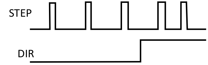
This mode is intended to be used by controllers to provide a Electronic Gearing source signal. The A line pulses for each step and the B line indicates the direction. Encoder Resolution (FB#.ENCLINES) is used to configure how many pulses per revolution there are.
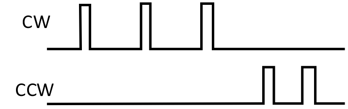
CW/CCW
As with Step/Direction, this mode is intended to be used as a Electronic Gearing source signal. The A line controls pulses in the clock wise direction and the B line control pulses in the counter-clockwise direction. Encoder Resolution (FB#.ENCLINES) is used to configure how many pulses per revolution there are.